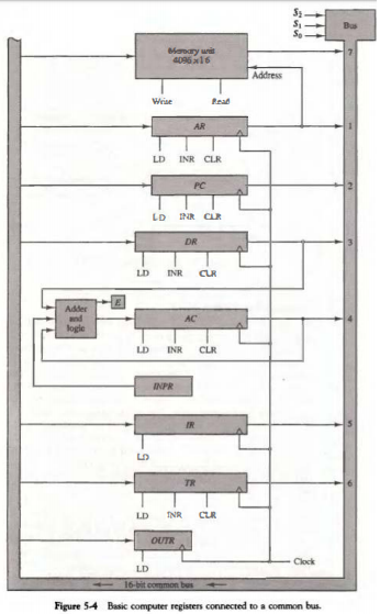
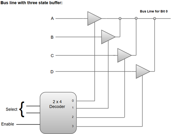
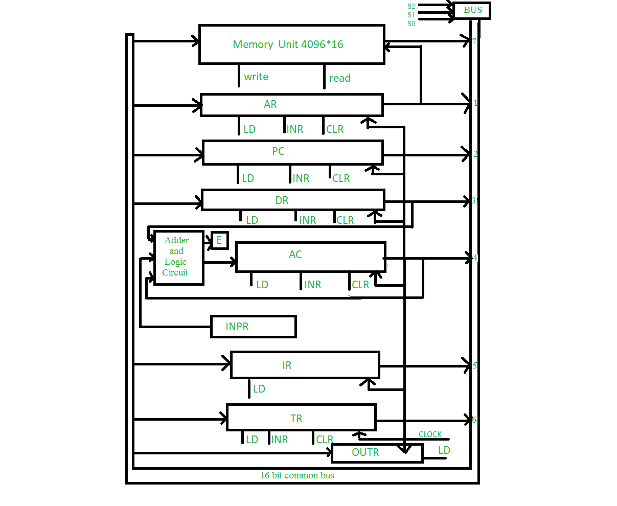
79+ pages construction of bus system for 8 register with 16 bits 1.7mb. A digital computer common bus system for 8 register of 4 bits each. Each multiplexer must have eight data input lines and three selection lines to multiplex one significant bit in the eight registers. The multiplexer select the one register who s information is transfer to another one destination register. Read also with and learn more manual guide in construction of bus system for 8 register with 16 bits The INPR receives character from input device and delivers it to the AC while the OUTR receives character from AC and transfers it to the output device.
The memory receives the contents of the bus when its write input is activated. The flag or F register is an 8-bit register whose individual flip-flops are set and reset by the ALU as the various arithmetic and logic operations are carried out.

Montage Electronique Simple Schema Electronique Pratique Montage Electronique Debutant Chargeur Solaire Electronique Simple Schema Electronique
| Title: Montage Electronique Simple Schema Electronique Pratique Montage Electronique Debutant Chargeur Solaire Electronique Simple Schema Electronique |
| Format: ePub Book |
| Number of Pages: 243 pages Construction Of Bus System For 8 Register With 16 Bits |
| Publication Date: June 2021 |
| File Size: 1.9mb |
| Read Montage Electronique Simple Schema Electronique Pratique Montage Electronique Debutant Chargeur Solaire Electronique Simple Schema Electronique |
 |
The particular register whose LD load input is enabled receives the data from the bus during the next clock pulse transition.

When AR or PC receive information from the bus only the 12 least significant bits are transferred into the register. The CY74FCT2574T can replace the CY74FCT574T to reduce noise in an existing design. 16-bit register is partitioned into two parts in d. One way of constructing bus system is by using multiplexers. 4 registers DR AC IR and TR have 16 bits and 2 registers AR and PC have 12 bits. A buffered clock CP and output-enable OE inputs are common to all flip-flops.
Coa Bus And Memory Transfer Javatpoint
| Title: Coa Bus And Memory Transfer Javatpoint |
| Format: ePub Book |
| Number of Pages: 343 pages Construction Of Bus System For 8 Register With 16 Bits |
| Publication Date: December 2019 |
| File Size: 2.3mb |
| Read Coa Bus And Memory Transfer Javatpoint |
 |

Construction Of Mon Bus System Using Multiplexer With Example In Puter Architecture Ca
| Title: Construction Of Mon Bus System Using Multiplexer With Example In Puter Architecture Ca |
| Format: eBook |
| Number of Pages: 140 pages Construction Of Bus System For 8 Register With 16 Bits |
| Publication Date: April 2019 |
| File Size: 3.4mb |
| Read Construction Of Mon Bus System Using Multiplexer With Example In Puter Architecture Ca |
 |

Cache Mapg Set Associative Mapg Example Memory Address Lecture Notes
| Title: Cache Mapg Set Associative Mapg Example Memory Address Lecture Notes |
| Format: eBook |
| Number of Pages: 174 pages Construction Of Bus System For 8 Register With 16 Bits |
| Publication Date: August 2019 |
| File Size: 2.8mb |
| Read Cache Mapg Set Associative Mapg Example Memory Address Lecture Notes |
 |

Bus Anization Of 8085 Microprocessor Geeksfeeks
| Title: Bus Anization Of 8085 Microprocessor Geeksfeeks |
| Format: PDF |
| Number of Pages: 178 pages Construction Of Bus System For 8 Register With 16 Bits |
| Publication Date: April 2017 |
| File Size: 1.5mb |
| Read Bus Anization Of 8085 Microprocessor Geeksfeeks |
 |

Check It Out Output Device Memory Address Logic
| Title: Check It Out Output Device Memory Address Logic |
| Format: eBook |
| Number of Pages: 185 pages Construction Of Bus System For 8 Register With 16 Bits |
| Publication Date: June 2021 |
| File Size: 1.7mb |
| Read Check It Out Output Device Memory Address Logic |
 |
Puter Anization And Architecture Mon Bus System Upsc Fever
| Title: Puter Anization And Architecture Mon Bus System Upsc Fever |
| Format: PDF |
| Number of Pages: 338 pages Construction Of Bus System For 8 Register With 16 Bits |
| Publication Date: September 2020 |
| File Size: 2.2mb |
| Read Puter Anization And Architecture Mon Bus System Upsc Fever |
 |
Mon Bus System Using Multiplexers Geeksfeeks
| Title: Mon Bus System Using Multiplexers Geeksfeeks |
| Format: PDF |
| Number of Pages: 282 pages Construction Of Bus System For 8 Register With 16 Bits |
| Publication Date: March 2017 |
| File Size: 6mb |
| Read Mon Bus System Using Multiplexers Geeksfeeks |
 |
Coa Bus And Memory Transfer Javatpoint
| Title: Coa Bus And Memory Transfer Javatpoint |
| Format: PDF |
| Number of Pages: 177 pages Construction Of Bus System For 8 Register With 16 Bits |
| Publication Date: August 2018 |
| File Size: 5mb |
| Read Coa Bus And Memory Transfer Javatpoint |
 |

Lab 11 Multiplexing Seven Segment Led Displays Embedded Lab Segmentation Circuit Diagram Seven Segment Display
| Title: Lab 11 Multiplexing Seven Segment Led Displays Embedded Lab Segmentation Circuit Diagram Seven Segment Display |
| Format: ePub Book |
| Number of Pages: 336 pages Construction Of Bus System For 8 Register With 16 Bits |
| Publication Date: April 2020 |
| File Size: 1.7mb |
| Read Lab 11 Multiplexing Seven Segment Led Displays Embedded Lab Segmentation Circuit Diagram Seven Segment Display |
 |

Lab 11 Multiplexing Seven Segment Led Displays Embedded Lab Segmentation Circuit Diagram Seven Segment Display
| Title: Lab 11 Multiplexing Seven Segment Led Displays Embedded Lab Segmentation Circuit Diagram Seven Segment Display |
| Format: eBook |
| Number of Pages: 156 pages Construction Of Bus System For 8 Register With 16 Bits |
| Publication Date: October 2017 |
| File Size: 1.3mb |
| Read Lab 11 Multiplexing Seven Segment Led Displays Embedded Lab Segmentation Circuit Diagram Seven Segment Display |
 |
Mon Bus System Geeksfeeks
| Title: Mon Bus System Geeksfeeks |
| Format: PDF |
| Number of Pages: 347 pages Construction Of Bus System For 8 Register With 16 Bits |
| Publication Date: December 2020 |
| File Size: 2.6mb |
| Read Mon Bus System Geeksfeeks |
 |
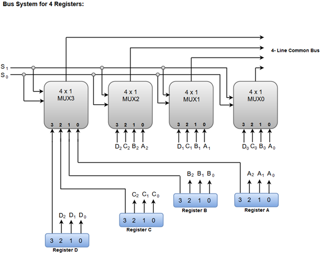
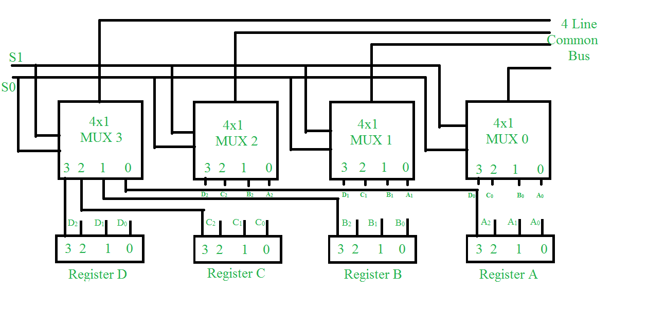
AT-Advanced Technology The improved AT bus also provided a total of 24 address lines which allowed 16MB of memory to be addressed. For instance a common bus for eight registers of 16 bits each requires 16 multiplexers one for each line in the bus. The bus consists of 41 multiplexers with 4 inputs and 1 output and 4 registers with bits numbered 0 to 3.
Here is all you need to read about construction of bus system for 8 register with 16 bits 5 registers have 3 control inputs LD load INR increment and CLR clear. The output 1 of register A is connected to input 0 of MUX 1 and similarly other connections are made as shown in the diagram. The lines from the common bus are connected to the inputs of each register and the data inputs of the memory. Check it out output device memory address logic coa bus and memory transfer javatpoint bus anization of 8085 microprocessor geeksfeeks lab 11 multiplexing seven segment led displays embedded lab segmentation circuit diagram seven segment display lab 11 multiplexing seven segment led displays embedded lab segmentation circuit diagram seven segment display montage electronique simple schema electronique pratique montage electronique debutant chargeur solaire electronique simple schema electronique With 16 bits a maximum of 2 16 65536 words can be addressed.